
Views: 0 Author: Site Editor Publish Time: 2026-06-03 Origin: Site


Data drift in emission monitoring does not just skew your daily reporting. It exposes industrial facilities to severe regulatory penalties and sudden, unplanned downtime. Relying on uncalibrated equipment often results in false alarms or undetected hazardous releases. Accurate measurement serves as your frontline defense against these compliance failures. However, harsh stack environments degrade sensor performance rapidly. Heat, moisture, and corrosive gases turn minor inaccuracies into major violations if left unchecked.
You need more than basic manual instructions to maintain measurement precision. This guide provides a compliance-focused, business-critical framework for calibrating emission tracking hardware. We cover everything from initial preparation to precise execution steps. You will also learn practical troubleshooting techniques for common bottlenecks. Finally, we explore the exact criteria for determining when legacy systems require complete replacement.
Compliance is driven by accuracy: Routine zero and span calibrations are mandatory to meet baseline environmental agency (e.g., EPA) standards and prevent audit failures.
Gas vs. Particulates: Calibrating a Fixed Source Emission Monitor for gases requires different protocols (certified reference gases) compared to calibrating an Automatic Dust/Gas Tester.
Proactive Risk Mitigation: Documenting environmental variables (temperature, humidity) and system drift during calibration prevents systemic measurement errors.
System Evaluation: Frequent calibration failures often indicate sensor degradation, signaling the need to evaluate modern, auto-calibrating monitoring solutions.
Regulatory bodies treat emission data as binding legal records. Agencies like the EPA mandate specific calibration frequencies and tight error tolerances under frameworks like Title 40 CFR Part 60. Failing an environmental audit disrupts operations immediately. Inspectors levy heavy fines for unverified emission logs. Authorities can even force complete operational pauses until you prove system accuracy. You simply cannot afford to treat routine calibration as an afterthought.
Sensor drift happens constantly in industrial settings. Harsh stack environments bombard analytical instruments relentlessly. High heat stresses electronic components. Moisture creates condensation inside sample lines. Corrosive gases degrade delicate sensor membranes over time. These physical realities mean analyzers inevitably lose their baseline accuracy. Regular calibration resets this accuracy and compensates for physical wear.
A successful calibration guarantees absolute data integrity. It builds verifiable, audit-ready data trails. These trails prove continuous compliance to regulators. Success means your analyzer readings match certified reference standards precisely. This alignment builds trust in your environmental reporting and protects your operational license.
Preparation prevents flawed calibrations. You must establish stable conditions before introducing any reference gases. Rushing this phase usually results in failed span checks.
First, verify your reference materials. Operators must use unexpired, NIST-traceable zero and span calibration gases. Local regulatory equivalents also work. Expired gases degrade inside the cylinder. They yield inaccurate target concentrations. Always check the certificate of analysis before opening a cylinder valve.
Next, execute thorough system purging and leak checks. You must inspect sample lines, probes, and conditioning systems. Look for blockages. Identify any micro-leaks. Ambient air leaking into the sample line artificially dilutes the calibration gas. This dilution causes failed span checks. Purge the lines completely to remove residual stack gases.
Finally, ensure environmental stabilization. The analyzer needs to reach its optimal operating temperature. Cold sensors respond sluggishly and inaccurately. Record ambient conditions like temperature and humidity in your logbook. These variables influence sensor behavior.
Table 1: Pre-Calibration Checklist | ||
Check Item | Action Required | Success Criteria |
|---|---|---|
Gas Cylinders | Verify expiration dates and concentrations. | NIST-traceable, unexpired, matching target range. |
Leak Diagnostics | Cap the probe tip and monitor pressure drop. | System holds vacuum; no ambient air intrusion. |
System Purge | Flush lines with instrument air or zero gas. | Readings drop to baseline; no residual target gas. |
Thermal Stability | Check analyzer and heated line temperatures. | All components reach manufacturer setpoints. |
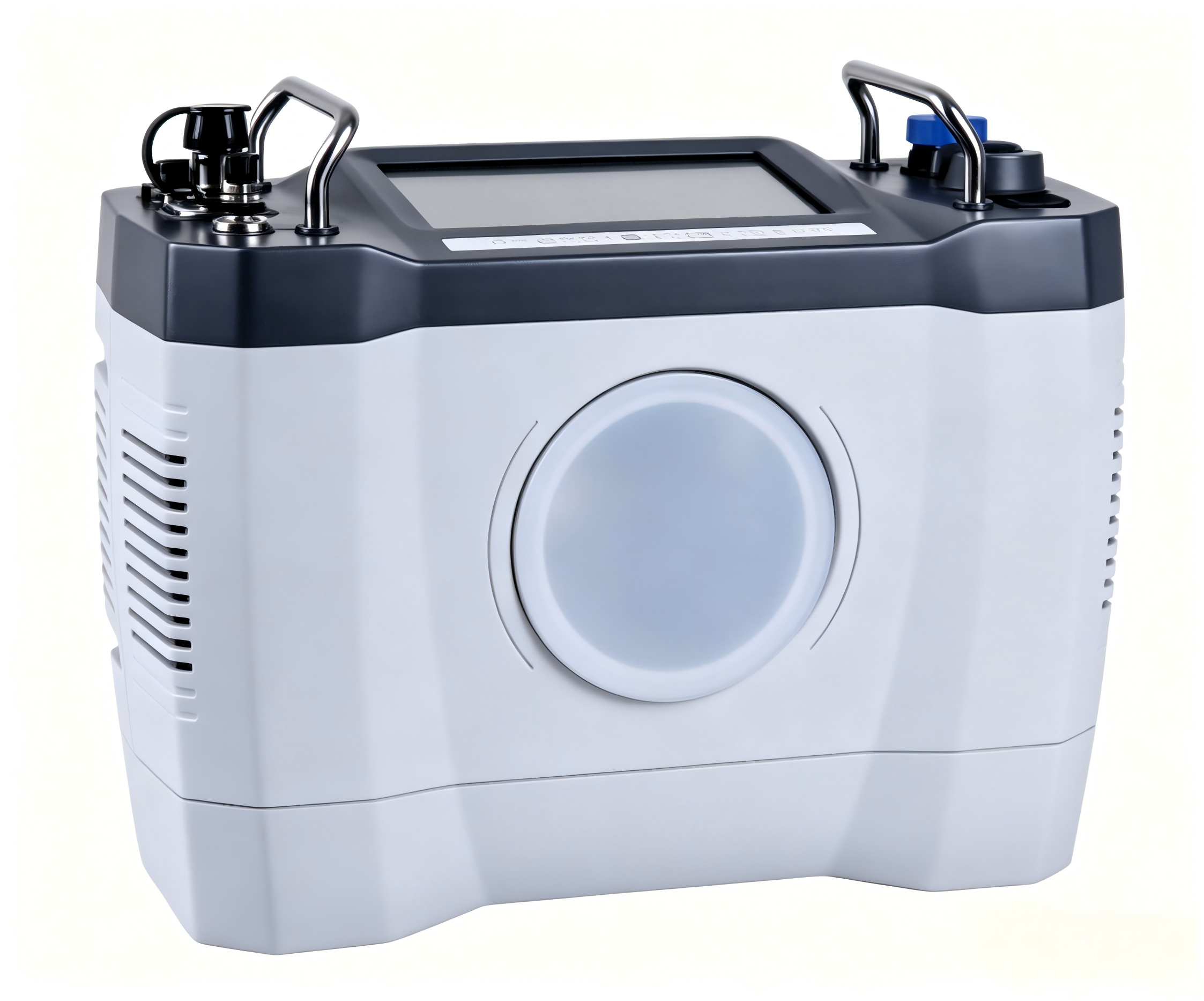
Following a strict standard operating procedure ensures consistency. You must perform these procedures methodically to maintain compliance. Here is the standard sequence for calibrating a Fixed Source Emission Monitor effectively.
Step 1: System Isolation: Switch the monitoring system to "maintenance" or "calibration" mode. This action prevents false alarms in the plant control room. It also stops skewed data from entering your environmental reporting software.
Step 2: Zero Calibration: Introduce high-purity zero gas to establish the baseline. Operators typically use nitrogen or zero air. Adjust the analyzer electronically or mechanically to read exactly zero.
Step 3: Span Calibration: Introduce the span gas. This cylinder contains a known, certified concentration of the target gas like SO2 or NOx. You usually set this concentration at 70 to 80 percent of the analyzer measurement range. Adjust the instrument to match the certificate value.
Step 4: Linearity and Response Time Testing: Verify the time it takes for the monitor to stabilize at the span value. Note any sluggish response. Slow stabilization times indicate potential filter clogging or severe sensor fatigue.
Step 5: System Restoration and Documentation: Purge the calibration gas from the lines completely. Return the system to standard sampling mode. Log the drift data meticulously for your compliance audit trail.
Gas and particulate monitors operate differently. Dust systems do not use gas cylinders for calibration. They require physical reference standards or precise gravimetric comparison methods.
When operating an Automatic Dust/Gas Tester, technicians must adapt their approach. You calibrate the gas modules using cylinders, but the dust module requires mechanical checks. We must separate these workflows entirely.
Consider the process for a β-ray Dust Direct Reading Tester. Beta-attenuation monitors measure the mass of particles collected on a filter tape. You establish the zero baseline using a clean, blank section of filter tape. Next, you introduce a calibrated reference foil. This foil simulates a precise particulate mass. The analyzer reads the foil and adjusts its span coefficient accordingly. This method verifies both the beta source intensity and the detector response safely in the field.
Optical and laser dust monitors require a different technique. They rely on light scattering principles. Technicians use scattering reference materials to calibrate them. You insert specific optical filters or scatter blocks into the measurement path. These blocks scatter light at predetermined intensities. They verify the baseline and span accuracy of the optical dust testers without requiring actual dust injection.
Sensors face extreme conditions daily. They frequently fail calibrations due to environmental interference or mechanical degradation. Recognizing these bottlenecks early saves valuable maintenance hours.
Sensor poisoning stands out as a critical failure mode. Poisoning occurs when cross-contaminating gases or excessive moisture irreversibly damage the detector. You will notice a complete lack of response to span gas. Recalibration cannot fix a poisoned sensor. You must replace the affected component immediately.
Flow rate discrepancies skew readings artificially. Pushing calibration gas at excessive pressure creates false high readings. Conversely, low flow starves the sensor. Ensure your flow meter matches the manufacturer specifications exactly. Always regulate the cylinder pressure properly before injecting gas.
Sample line integrity often causes frustrating headaches. Sticky gases like ammonia or hydrogen chloride adhere to Teflon or stainless steel tubing. This adherence causes delayed response times. The analyzer might fail the calibration simply because the gas takes too long to reach the sensor. Heating the sample lines usually resolves this specific issue.
Troubleshooting Common Calibration Errors | ||
Symptom | Probable Cause | Recommended Action |
|---|---|---|
Analyzer reads zero during span gas injection. | Empty cylinder or closed valve. | Check cylinder pressure and primary regulator. |
Sluggish response time (> 3 minutes). | Clogged inline filter or sticky gases. | Replace particulate filters and check line heaters. |
Drift exceeds regulatory limits daily. | Sensor degradation or thermal instability. | Evaluate sensor lifespan and check enclosure HVAC. |
Span calibration fails consistently. | Sensor poisoning. | Replace the sensor and investigate stack gas cross-sensitivity. |
Old hardware eventually becomes an operational liability. Operators must establish a strict decision framework for equipment replacement. You reach the tipping point when an instrument requires excessive daily maintenance. If an analyzer fails linearity tests repeatedly, recalibration just wastes time. Severe daily drift indicates fundamental hardware degradation. Calibration no longer serves as a viable fix in these scenarios.
Modern monitoring systems offer significant operational advantages over legacy equipment. Look for these key features when shortlisting new continuous emission systems:
Automated Daily Calibration: Modern units cycle zero and span gases automatically. They remove manual intervention from daily routines and eliminate human error.
Advanced Diagnostics: Built-in predictive maintenance alerts prove invaluable. They monitor detector voltage and flow rates continuously. They flag sensor degradation weeks before an official audit failure occurs.
Multi-Component Capability: Facilities increasingly transition from single-gas analyzers to integrated setups. These advanced systems handle both gas and particulate tracking simultaneously in a single rack.
Next steps require decisive action. Operators should evaluate their current manual calibration schedule against investing in a modernized, compliance-ready system. Modernizing your hardware eliminates data gaps, reduces weekend call-outs, and secures your operational license against increasingly strict environmental regulations.
Rigorous calibration represents the foundation of industrial compliance and operational security. It is never just a technical checklist. Accurate baseline adjustments prevent audit failures and protect your facility from severe regulatory penalties. Relying on outdated equipment with high drift rates poses an unacceptable business risk in today's regulatory environment.
You must establish strict routines for both gas analyzers and particulate testers. Documenting every variable ensures your data stands up to external scrutiny. We encourage you to consult with an environmental monitoring specialist today. Audit your current calibration standard operating procedures or request a technical demonstration of advanced, low-maintenance emission monitors to secure your compliance future.
A: Regulatory standards typically require daily automated zero and span checks to verify immediate accuracy. Comprehensive audits, including multi-point linearity tests and cylinder gas audits (CGAs), usually occur quarterly. Full relative accuracy test audits (RATA) are mandated annually to ensure long-term compliance.
A: Zero gas contains zero concentration of the target analyte. It establishes the baseline or "zero" point of the analyzer. Span gas contains a precise, certified high-level concentration of the target gas. It sets the upper scale or sensitivity of the sensor.
A: Yes, you can perform field verifications using blank filter tapes and certified reference foils. The blank tape sets the zero baseline, while the reference foil simulates a specific particulate mass to verify span. However, absolute gravimetric calibration often requires laboratory comparison.
A: This often happens if you inject calibration gas directly into the back of the analyzer instead of through the entire sample probe and heated line. System-level calibration is necessary to reveal leaks, blockages, or gas adherence issues hidden within the sampling infrastructure.


